Addressing the Class D bias
The “D” in Class D does not stand for digital. It was simply the fourth type of amp recognized and classified by the IEEE. The first was Class A, the second Class B, the third Class C, etc.
Contrary to the bias that exists among high-end enthusiasts and across the industry in general, the Class D design is not inherently flawed. The truth is that no existing designs have been able to reach the Class D’s inherent potential for performance. It is not the technology that yields fine audio performance but rather the implementation of the technology. At Anthem, we agree that most Class D amplifiers are poor performers. However the M1 uses Class D amplification of a different ilk (see later section on Class D for a full discussion).
The M1 is not a digital amp!
There are no A/D or D/A converters in the signal path. The amplifier’s control system continuously varies the width of the output pulse train in direct relation to the analog input signal. In essence, a side-to-side variation in width is analogous to a signal’s more familiar up-and-down amplitude variation, not at all the same as a digital string of 1s and 0s where all pulses have the same width.
Exceptional efficiency
Much has been written about Class D amps having twice the efficiency of conventional amplifiers at full output, but there’s more to this. Under normal conditions an amplifier operates at only a fraction of its full output capability. At 1/8th of its maximum output (the typical working level of an amplifier), our M1 is six times more efficient than a conventional amplifier.
Advanced Load Monitoring & Power Factor Correction
Proprietary Load Monitoring
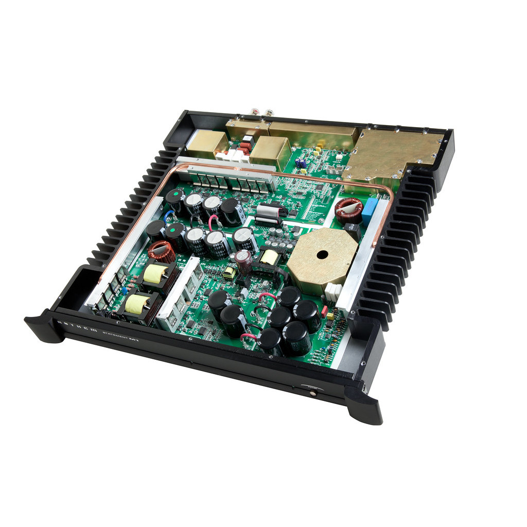
The M1 has a very sophisticated load monitoring system. Two 100A Hall-Effect sensors monitor the output current. A Digital Signal Processor, outside the signal path, is used for power sequencing and to monitor various amplifier and power supply functions including line voltage, output current, ground fault detection, temperature and DC voltage at the output.
The M1’s output stage does not interact with the load. A hysteric PID controller which uses past, present and a predicted future to make adjustments keeps the amp load independent. Hundreds of computer simulations were used to test and optimize this system so that it is able to handle all possible loads. This is a significant design achievement. Whether you are running the M1 from a 120V circuit or a 240V circuit, the amplifier will be delivering the highest output possible according to the operating conditions.
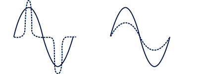
Left: Power supply without PFC. Current flows in short bursts and ends up much higher than it needs to be, limiting available power and increasing the chance of tripping a breaker.
Right: Power supply with PFC. The voltage and current waveforms are sinusoidal and in-phase.
Power Factor Correction
Power Factor Correction (PFC) maximizes available power and at the same time reduces (by a large amount!) the noise put on the AC line. Without PFC, the input current can flow and charge the capacitors only during the short moments that voltage is at or very close to its positive or negative peak. Since power is the product of both voltage and current it is produced only when both are present. Power Factor Correction marries the voltage and current cycles enabling continuous output from the power supply through the entire AC cycle. In doing so, the load appears almost purely resistive to the AC source. (See diagrams to right)
The special advantages of bridged mode amplification in the M1
Additional high-end touches





Reviews
There are no reviews yet.